
The building and the performance objective
You will assess an existing four-story steel moment frame with a pushover analysis in the X direction. The example is deliberately small so that every step is easy to repeat, and it is a tutorial: it shows how the workflow fits together, not how to certify a building.
| Plan | 4 bays in X and 2 bays in Y, all 24 ft (288 in) |
| Height | 4 stories at 13 ft (156 in), fixed bases |
| Members | W14x90 columns, W24x76 beams, expected yield strength Fye = 54 ksi (1.5 × 36 ksi) |
| Floors | 4.5 in concrete slab as an elastic shell, rigid diaphragm at every story |
| Loads | Slab, beams and columns self-weight, plus 20 psf superimposed dead and 40 psf live |
| Hazard and target | BSE-2E, Collapse Prevention (CP) |
| Analysis | Gravity (Dead + 0.25 Live), then a displacement-controlled pushover in X |
The W14x90 columns are lighter than the W24x76 beams frame into them, so the columns hinge before the beams. The example keeps these sections on purpose: it shows the fiber-section column hinges at work. Do not read the result as a recommended design.
vfopro does not calculate an ASCE 41 target displacement and does not check acceptance criteria against a demand. This guide stops at the pushover curve, hinge status and interstory drift. The engineer of record chooses the target displacement, load pattern and acceptance checks.
Open SteelMRF_4x2.vfodb from Home › Load Model to jump to step 6. Save a copy first with Save As.
1. Set up
-
Click New Model on the Home panel, then Save As and save the model in a folder you own. Analysis needs a saved file, and saving now means the autosave never overwrites something else.
-
Open Unit System and leave it on kip · in · sec. Mass is only computed correctly in this system, so do not switch to kip · ft.
2. Build the geometry
-
Open Create › Grid System › Grid Data. Enter five X grids (tags
AtoEat0,288,576,864,1152) and three Y grids (tags1to3at0,288,576), then click Save.You should see: “Grid data saved successfully! X Grids: 5 Y Grids: 3”. -
Open Story Data and add four levels:
Level 1at156,Level 2at312,Level 3at468andLevel 4at624. Click Save.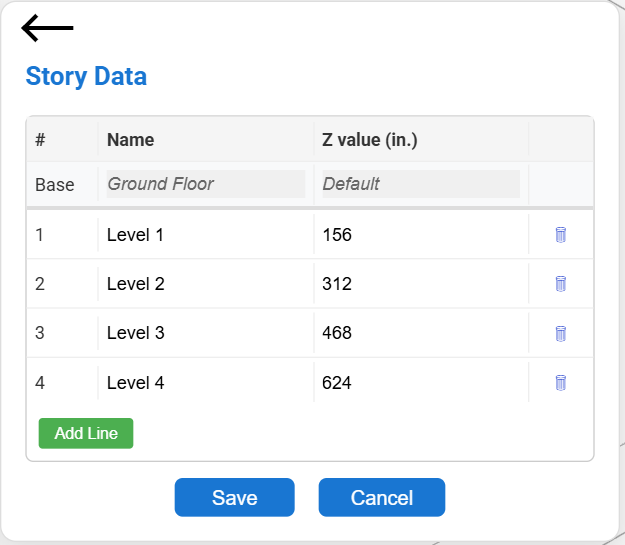
Create › Grid System › Story Data. -
Open the plan view of Level 1 and draw one story: a column at each of the 15 grid intersections, the 22 beams that join them along the grid lines, and the 8 shell quads (one per bay) that make the slab. Drawing the beams and quads at Level 1 only is faster than drawing all four levels.
You should see: 15 columns, 22 beams and 8 quads on Level 1 in the 3D view. -
Select everything at Level 1 and use Replicate by story to copy it to Levels 2, 3 and 4.
You should see: 60 columns, 88 beams (48 in X and 40 in Y) and 32 quads in total.
In the current build the column tool creates nodes without elements until a section and material have been chosen. This is being tracked separately; the final steps here will be updated once it is fixed.
3. Materials and sections
-
Define one steel material for the fiber columns: a Steel02 uniaxial material with E =
29000ksi, Fy =54ksi (expected yield) and post-yield ratio b =0.01. -
Define the elastic frame sections
W14X90(columns, used for the elastic model and self-weight) andW24X76(beams), then a fiber W section for the column hinges: Define › Sections › Frame › Fiber W section with AISC shapeW14X90and the Steel02 material. -
Define the slab as an elastic shell section, 4.5 in thick with the 4 ksi concrete material.
-
Assign
W14X90to all columns,W24X76to all beams and the shell section to all quads. Select the 15 base nodes and assign a fixed restraint (all six degrees of freedom).
4. Define and assign hinges
Hand calculation for the beam hinges
vfopro does not derive beam hinge properties from the section. You supply them from ASCE 41 Table 9-7 for a compact W-shape beam. For a W24x76 with Zx = 200 in³, Ib = 2100 in&sup4; and an assumed 288 in span:
- Yield moment,
My = Zx × Fye = 200 × 54 = 10,800 kip-in. - Yield rotation,
θy = Zx · Fye · Lb / (6 · E · Ib) = 200 × 54 × 288 / (6 × 29000 × 2100) = 0.00851 rad. - Backbone: plastic rotation
a = 9θy,b = 11θy, residual strengthc = 0.6. - Acceptance rotations for a beam: IO =
1θy, LS =6θy, CP =8θy.
These factors are for review by a qualified engineer against the edition of ASCE 41 you are using before this guide is published. Never publish or rely on numbers you have not checked.
-
Open Define › Hinges › Frame › Moment-Rotation and create a hinge named for the beam. Yield moment
10800. Moment scale factors1, 1.03, 0.6, 0.6and rotations9θy, 9.09θy, 11θy(0.0766, 0.0774, 0.0936rad). Limit states IO/LS/CP at0.00851,0.0511and0.0681rad.Why 1.03 and not 1.0The backbone needs a small positive slope in its second segment. The strength rises from 1.0 to 1.03 of My over a rotation of 0.09θy, then falls to 0.6.
-
Select the 48 beams that run in the X direction and open Assign › Frame Elem › Hinges › Compound Component. Choose the moment-rotation hinge with length
0, and a rigid end zone. Leave the 40 Y-direction beams elastic with no hinges; you push in X only. -
Select the 60 columns and open Assign › Frame Elem › Hinges › Beam Integration › Conc. Curvature. Choose the fiber W14x90 section and set the plastic-hinge length
Lp = 7in at both ends (about half the 14 in column depth).
5. Diaphragms, loads, mass and load cases
-
Diaphragms. Define a rigid diaphragm for each story and assign it to that story’s nodes. Use one constraint per story; sharing a single constraint between stories does not run.
-
Load patterns. Create
Dead(self-weight multiplier 1),SDL(dead type, self-weight 0),LiveandPushX. Dead carries the weight of the beams, columns and slab. -
Superimposed and live loads. Apply them as downward nodal loads at every floor node: tributary area (half a bay each side of the node, or a quarter of the bay at a corner) times 0.020 ksf (SDL) and 0.040 ksf (Live). Each floor then carries 4608 ft² of load:
Node type Tributary area SDL (kip) Live (kip) Corner (4 per floor) 144 ft² 2.88 5.76 Edge (8 per floor) 288 ft² 5.76 11.52 Interior (3 per floor) 576 ft² 11.52 23.04 -
Pushover pattern. In
PushX, apply an X force at the centre node of each floor, in proportion to height:1,2,3and4kip at Levels 1 to 4 (an inverted triangle). -
Mass source. Add a mass source that takes
DeadandSDLat a factor of 1. Live load is not part of the seismic mass in this example. -
Load cases. Create three cases:
Modal: 6 modes.Gravity: static, Dead 1 + SDL 1 + Live 0.25.PushoverX: nonlinear static, displacement control, initial conditionGravity, patternPushX, control node the roof centre node, DOF1, target30in in300steps.
-
Drift stack. Define an interstory drift node stack up one column line so the drift profile is available in the results.
-
Run Analysis › Check Model, then save.
You should see: 0 errors and 0 warnings, and a total weight of about 1746 kip.
6. Run the analysis
-
Reopen the saved model with Load Model before you run it. The hinge results view needs the export map that is created when the model is loaded from the file.
-
Open the Analysis panel, tick
Modal,GravityandPushoverXand run. Watch the Convergence Monitor.You should see: Gravity finishing in 10 of 10 steps and PushoverX in 300 of 300.The Modal case reads “Failed”The Modal case can show a “Failed” label even though the periods were computed and printed. The first period is about 0.417 s.
7. Read the results
-
Base shear versus displacement. Build the plot from the Report builder’s Baseshear–Displacement widget for
PushoverX.You should see: a peak base shear of about 2286 kip at the full 30 in of roof displacement, with the stiffness softening steadily as the columns yield. -
Hinge status. Open Post Processing, select Load Case › PushoverX, tick Hinges › Frames once and click OK. Drag the animation slider to a step. Green is up to IO, yellow between IO and LS, red beyond.
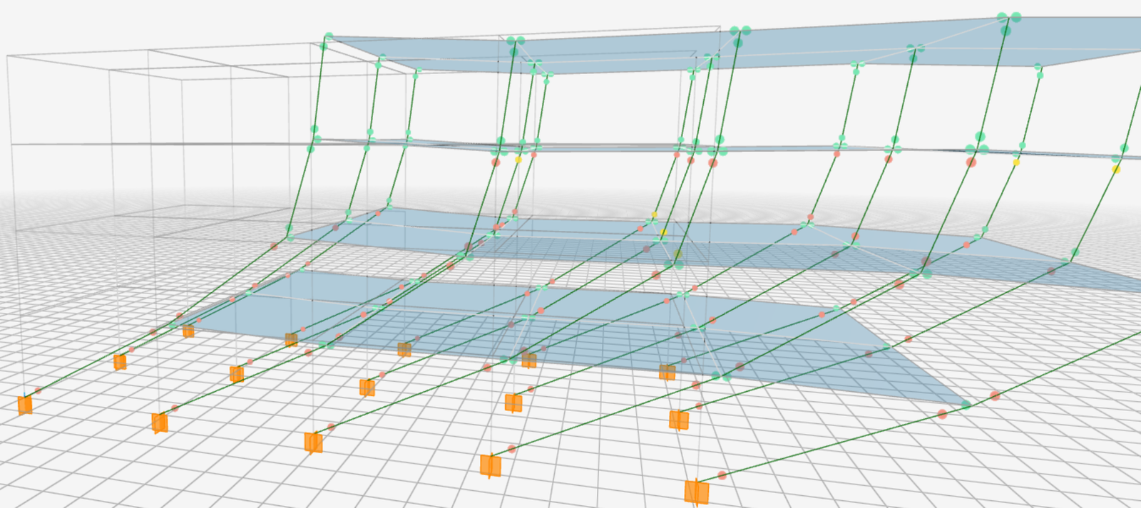
Post Processing › Hinges › Frames at the last step (deformed shape magnified). You should see: all 96 beam hinges still green (largest rotation about 3×10⁻⁷ rad) and the first column hinge reaching CP around step 100–113, at a roof displacement of about 10 in. -
Interstory drift and the report. Open the IDR chart for the drift stack you defined, then use the Report builder to add the base-shear, IDR and hinge-summary widgets and export to PDF or HTML.
The hinge summary in the report covers the moment-rotation beam hinges. The column fiber hinges are shown in the Post Processing overlay; their summary is not in the report.
Your responsibilities
- The engineer of record selects the seismic hazard, target displacement and acceptance criteria. vfopro does not calculate a target displacement or check acceptance for you.
- This example uses one simplified lateral pattern and a single direction. A real assessment normally uses more than one pattern and both directions, plus an accidental-torsion check.
- Y-direction beams are elastic and columns yield first here. The result demonstrates the tool, not the adequacy of the building.
- Check the ASCE 41 numbers in step 4 against the edition you use.
Last updated September 21, 2026 · applies to vfopro 20260921.0.0 or later